Posts

Showing posts from 2018

Install TurtleBot on ROS Kinetic (Ubuntu 16.0.4)
Image
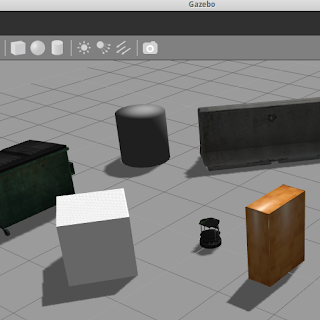
I faced a lot of problem while installing the TurtleBot on the ROS Kinetic. Follow this to install it successfully: sudo apt-get install -y linux-headers-generic sudo apt-get update sudo apt-get install ros-kinetic-librealsense sudo apt-get install ros-kinetic-turtlebot* sudo apt-get install ros-kinetic-ar-track-alvar-msgs Type " roslaunch turtlebot_ " and press tab twice. If you get the following packages,it is successfully installed !

Hexcopter

Image
Finally, I completed making my first drone. I wanted to make something new so I chose to make a Hexacopter. Its the first Hexacopter ever made in my college. Above is the video of its first flight test. The Hexacopter is an under-actuated, dynamic vehicle which uses six rotors to push air downwards to create a thrust force for keeping the hexacopter on the air. They offer higher power abilities hence it can have much better elevation and speed controls as compared to quadcopters. UAV(Unmanned Aerial Vehicles) are gaining popularity for their capability of flying without an onboard pilot. They can be controlled using an operator autonomously. The interest of the research community for Unmanned Aerial Vehicle (UAV) design is fast growing up with the aim of developing cheaper and more capable machines. Flight Controller: APM 2.8 The flight controller is the mind or ‘brain’ of the Hexacopter. This board is what sits at the center, controlling the firmware within the ESCs, cons

LiPo batteries

Image
Lithium Polymer batteries are widely used in various devices as in drones and multi-copter for its ability of recharging. When you look at the battery there are two sets of wires coming out of it. One set is a pair of thick wires, one red for positive and the other black for negative. These are usually used in RC electronics especially for multi rotors and planes where the battery is discharged quickly ! The other set of wires contains the number of black wires which is equal to the number of cells in the battery and one red wire. It is for balance usage i.e. equal amount of current is drawn from all the cells so at any point, the voltage of all the cells remain the same. The voltage of the battery shown is the total voltage of all the cells included. Note that all the cells of the battery are connected in series. One cell of a battery has a nominal voltage of 3.7V . When fully charged it goes up to 4.2 V per cell. It can go upto 3V at a minimum. If it goes below, the cell gets dam

Tech Talk 2 : The Internet

Image
We have been talking about various things on this blog for a while now, but do you know what makes this information reach out to you ? Do you really know what Internet is ? Internet is global network of interconnected computers that use Internet suite protocol TCP/IP to link devices world wide. It uses telephone lines, cables, satellites and wireless connections to connect computers to World Wide Web. Data Transmission Internet is a lot like the postal service. Instead of posts, information is transmitted. This information is in form of bits. Bits signifies a pair of opposites. Like on or off, high or low, 1 or 0. We add a clock to it to keep a track of these bits. There are three ways to communicate this data. The first being Electricity. Imagine the on and off of a light bulb. Lets say we transmit 1 bit per second. If the light bulb is on for 2 seconds and then gets turned off for 1 second, we say the data is 110. An example of this type of transmission is the Ethernet cable w

Getting Started with NodeMCU ( ESP8266 )

Image
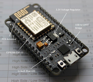
Till now we have been talking about Arduino and stuff related to it. In this post we will be talking about another type of micro-controller i.e. NodeMCU. It is a wifi module chip which can be connected to internet for IoT ( internet of things ) projects. Introduction NodeMCU is a open-source IoT platform. It has the firmware which works on ESP8266 WiFi Soc and hardware which is based on Esp-12 module. Soc ( System of chip ) is an integrated circuit which integrates all the components of a computer. It uses the LUA scripting language. There are two ways to program it. One is with ESPlorer IDE using the Lua scripts. Another is using the Arduino IDE. All you need to do in the IDE is : File ->  Preferences -> Enter http://arduino.esp8266.com/versions/2.4.1/package_esp8266com_index.json   -> OK Tools -> Boards -> Board manager -> Install ESP8266 boards ESP8266 The ESP8266 is a 32-bit low-cost Wi-fi microcontroller produced by Chinese manufacturer, Espressif

Serial Communication : I2C

Image
Hey there ! In the last two posts we talked about the the types of serial communication which were UART and SPI. In this post we are going to talk about another type of serial communication which is the Inner-Integrated Circuit or I2C. The barometric pressure sensors and gyroscopes/accelerometers use this kind of protocol. Introduction to I2C I2C is also called Two Wire Interface (TWI) since it requires only two wires for communication. It was developed by Philips in 1982. With it, we can connect multiple slaves to a single master ( like SPI ) and multiple masters to a one or more slaves. SDA : Serial Data - The line for the master and slave to send and receive data. SCL : Serial Clock - The line that carries clock signals. If we look at Uno, pin A4 is for SDA and pin A5 is for SCL. Just like SPI, the data transfer is synchronous i.e. the timing of the output and sampling of bits takes place with a clock signal shared by the master and the slave. Each device can be a mast

Serial Communication : SPI

Image
In the last post we discussed UART , which was a type of serial communication between devices. In this post we are going to talk about another type of serial communication which is SPI. SPI communication is used by a number of devices like the RFID card reader, SD card module, etc. Introduction to SPI SPI stands for Serial Peripheral Interface. It was developed by Motorola in 1979. Device communicating via SPI are in master-slave relationship. The master as the name suggests is the controlling device and the slave is the one who takes instruction from the master. There can a number of slaves under one master. MOSI : Master Output Slave Input - Line for master to send the data to the slave. MISO : Master Input Slave Output - Line for slave to send data to the master. SCLK : Clock - Line for the clock signal SS/CS : Slave select/Chip Select : Line for the master to select the slave to send data to. So, at least four wires are required for this communication. More

Serial Communication - UART

Image
Many of you would be aware about two types of communications : Serial and Parallel. Coming to Arduino, it communicates with computers or other devices using serial communication. In this type of communication, data is transmitted between two devices one bit at a time. The most common type of serial communication is UART. Introduction to UART UART stands for Universal Asynchronous Receiver Transmitter. It takes bytes of data and transmits it in a sequential fashion. At destination, a second UART re-assembles these bits into complete bytes. The communication may be simplex ( one direction only), full duplex ( both devices send and receive at the same time), half-duplex ( device takes turns to transmit and receive). For UART communication we need COM ( for communication ) ports. But modern computers does not include them and we need external serial to USB converter when using other micro-controllers. Arduino has an on board serial to USB converter so we can directly connect it to

Tech Talk 1 : Servo Motors and PWM

Image
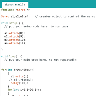
I bring to you a new series called "Tech Talk". It will be different from my normal posts where I explain different topics. As its name says, it will be more of an informal talk where I will put forth a question or a topic and then brainstorm the answer to it ! While playing with servo motors, I came across an interesting concept of pulse width modulation connected to the servo motors which I will be discussing here. Servo library has to be called and an object has to be made in the IDE for controlling the servo motor. Once we do that we use object_name.write() and specify the angle which the servo should be turned to. Servo control is actually achieved by sending a PWM signal to the servo motor. But since there are only 6 PWM pins on the Arduino Uno does that mean we can connect only 6 servos to it ?  For comparison I used the same servo on both PWM as well as non-PWM pins on the Arduino and there was no visible performance difference ! If PWM is used by servos,

Analog and Digital Signals

Image
In this post we are going discuss something which is used in all the electronics and computers which is the Pulse Width Modulation and the concepts related to it. Logic level is the voltage level that a particular device communicates with. A common logic level that a micro-controller uses is 5V. An analog varies from 0V to 5V for example as a sine wave. So, at any point of time we can get any value between 0 and 5 volts in the case of the analog signal. On the other hand digital signal can have only two values 0V or 5V just like the on or off. Analog to Digital Digital signals are more efficient since the analog signals have a lot of noise in them. So, we usually convert the analog to digital. The analog to digital converter on the Arduino is of 10-bit which means we have 2^10 = 1024 resolutions. Thus the analogRead() reads the analog value from 0 to 5 volts and assigns it a digital value from 0 to 1023. Whereas the digitalRead() reads either high (1) or low (0). The analogWrit

Overview of ATmega328P

Image
While reading about the ATmega328, I came a across a lot of stuff which I would like to share here. There is a humongous amount of information available in its datasheet. Introduction ATmega328 is a single chip micro-controller created by Atmel. It has a In-System Self-programmable Flash memory of 32 KB, SRAM of 2 KB (2048 bytes) and EEPROM of 1 KB (1024 bytes). It has a 8-bit AVR CPU type which means they can process data in 8-bit chunk as its data bus is 8-bit wide.   It contains 23 general purpose I/O pins and 32 general purpose working registers. It has 32 single-byte registers and 8-bit RISC (reduced instruction set computer) devices and hence the name 328. The P is for ' picoPower '. It has 3 flexible timer/counter with compare modes, internal and external interupts , 6-channel 10-bit A/D converter , programmable watch dog timer with internal oscillator and 5 software selectable power saving modes. Digital communication peripherals include 1-USART, 2-SPI and 1-I

Arduino Bootloader

Image
Ever wondered how the code written in the IDE is actually executed ? Do you know where is the code stored in the Arduino and how does it get updated ? ATmega328P is the chip usually used in Arduino uno and nano. When the sketch is loaded it is actually loaded inside the micro-controller chip. This chip then runs the sketch once the Arduino is powered up. Almost all the micro-controllers use some form of a bootloader. When a micro-controller turns on,it runs a specific thing at a particular location (mostly 0x0000). This location usually contain a jump instruction to another place in the memory which is the start of the user program. The bootloader ,however, exits at a different memory location. On a power-up or reset, a bootloader is a section of memory that runs before the main code runs. It is used to setup the micro-controller or provide ability to update main program's code. The Arduino Bootloader supports re-programming the flash memory over serial. Like other micro-

Arduino for Beginners

Image
The first toy which I came across in my endeavor in robotics was the Arduino Uno !  "Arduino" is an open-source computer hardware and software company which manufactures development boards. It designs single board micro-controllers such as uno ,mega,nano. It is basically the brain of the robot. It takes in input, process it based on the code and gives the desired output.   It is programmed using the C code but since it is cumbersome , Arduino firmware is loaded on ATmega chip which allows us to use the user-friendly Arduino programming language. The Arduino IDE is a cross-platform application which is written in Java.The program written in it is called a "sketch".  The setup() function : It is called once when it starts or resets.The variables and I/O pins are initialized here. The loop() function : As the name suggests it repeats itself continuously. Arduino Uno is the most popular board. It is an open-source micro-controller based on ATmega328pu.

The Pilot

Welcome to my blog.. This space is all about the projects that I have worked on and the stuff that I find very interesting and engaging. Content is mostly the stuff which will not be covered in curriculum. I am currently a first year student pursuing Mechanical Engineering at BITS Pilani Hyderabad campus. Lastly, I do not claim that what I write is utmost truth and feel free to search what goes beyond the topic ! This is my contribution to the field of robotics, micro-controllers and automation. I hope that it shall be of help to the reader in his/her endeavors. Also feel free to leave comments, ask questions, offer suggestions to make this blog a better place !