Serial Communication : I2C

Hey there ! In the last two posts we talked about the the types of serial communication which were UART and SPI. In this post we are going to talk about another type of serial communication which is the Inner-Integrated Circuit or I2C. The barometric pressure sensors and gyroscopes/accelerometers use this kind of protocol.
Introduction to I2C
I2C is also called Two Wire Interface (TWI) since it requires only two wires for communication. It was developed by Philips in 1982. With it, we can connect multiple slaves to a single master ( like SPI ) and multiple masters to a one or more slaves.
 SDA : Serial Data - The line for the master and slave to send and receive data.
SCL : Serial Clock - The line that carries clock signals.
If we look at Uno, pin A4 is for SDA and pin A5 is for SCL. Just like SPI, the data transfer is synchronous i.e. the timing of the output and sampling of bits takes place with a clock signal shared by the master and the slave. Each device can be a master or a slave or both at different times.
How it Works ?
The data is transferred in form of messages. It has start condition, the address frame, read/write bit and the ACK/NACK bit. Once all that are transmitted, the data is transferred with each frame followed by a ACK/NACK bit. The end is marked with a stop condition. Note that one bit is transferred in one clock cycle.
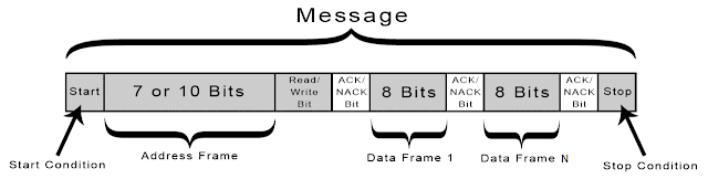
Start Condition : The SDA line switches from high to low indicating a transfer of a message. Note that this takes place before the SCL line switches from high to low. The clock is controlled by the master and this is initiated by it.
Address Frame : It is a 7 to 10 bit unique sequence that identifies the slave to which the master wants to talk to. It is always the first frame after the start bit.
Read/Write Bit : It is a single bit specifying whether a master wants to send data to the slave or receive from it. If the master wants to send data to the slave, the bit is set low and if it want to receive data from the slave, the bit is set high.
Slave acknowledgement - ACK/NACK : Each data transfer is followed by a acknowledge/no-acknowledge bit. If the data was received successfully, an acknowledge bit is returned to the sender by the receiving device. It is set by the slave.
Data frame : It contains the actual data to be transmitted. Each data frame is 8 bit long and is sent with most significant bit first. Each data frame is followed by a ACK/NACK bit to verify that the frame is received successfully.
Stop Condition : The SDA lines switches from low to high indicating an end of the transfer. Note that this takes place after the SCL line switches from low to high.
First, the master sends the start condition. Since I2C does not have the slave select pin, it sends the address frame. The master sends this address frame to each of the slave. The slave compares this address with its unique address. If it matches, the slave sends a low voltage acknowledge bit back to the master by pulling the SDA line low. If it does not, slave does nothing and the SDA line remains high.

Upon receiving the ACK bit from the slave, the first data frame is sent. The data frame is followed by a ACK/NACK bit to confirm the successful transmission of data. The ACK bit must be received either by the master or the slave ( depending upon who is sending) before next data frame is sent. After the data transfer is complete, the stop condition is executed.

Introduction to I2C
I2C is also called Two Wire Interface (TWI) since it requires only two wires for communication. It was developed by Philips in 1982. With it, we can connect multiple slaves to a single master ( like SPI ) and multiple masters to a one or more slaves.

SCL : Serial Clock - The line that carries clock signals.
If we look at Uno, pin A4 is for SDA and pin A5 is for SCL. Just like SPI, the data transfer is synchronous i.e. the timing of the output and sampling of bits takes place with a clock signal shared by the master and the slave. Each device can be a master or a slave or both at different times.
How it Works ?
The data is transferred in form of messages. It has start condition, the address frame, read/write bit and the ACK/NACK bit. Once all that are transmitted, the data is transferred with each frame followed by a ACK/NACK bit. The end is marked with a stop condition. Note that one bit is transferred in one clock cycle.
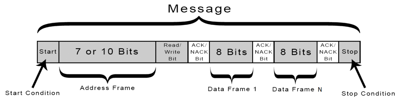
Start Condition : The SDA line switches from high to low indicating a transfer of a message. Note that this takes place before the SCL line switches from high to low. The clock is controlled by the master and this is initiated by it.
Address Frame : It is a 7 to 10 bit unique sequence that identifies the slave to which the master wants to talk to. It is always the first frame after the start bit.
Read/Write Bit : It is a single bit specifying whether a master wants to send data to the slave or receive from it. If the master wants to send data to the slave, the bit is set low and if it want to receive data from the slave, the bit is set high.
Slave acknowledgement - ACK/NACK : Each data transfer is followed by a acknowledge/no-acknowledge bit. If the data was received successfully, an acknowledge bit is returned to the sender by the receiving device. It is set by the slave.
Data frame : It contains the actual data to be transmitted. Each data frame is 8 bit long and is sent with most significant bit first. Each data frame is followed by a ACK/NACK bit to verify that the frame is received successfully.
Stop Condition : The SDA lines switches from low to high indicating an end of the transfer. Note that this takes place after the SCL line switches from low to high.
First, the master sends the start condition. Since I2C does not have the slave select pin, it sends the address frame. The master sends this address frame to each of the slave. The slave compares this address with its unique address. If it matches, the slave sends a low voltage acknowledge bit back to the master by pulling the SDA line low. If it does not, slave does nothing and the SDA line remains high.

Upon receiving the ACK bit from the slave, the first data frame is sent. The data frame is followed by a ACK/NACK bit to confirm the successful transmission of data. The ACK bit must be received either by the master or the slave ( depending upon who is sending) before next data frame is sent. After the data transfer is complete, the stop condition is executed.


Comments
Post a Comment